

DPA Confirmation confirms the reception of DPA Request by interface slave to interface master at the [C]. It consists of the same foursome that was part of the original DPA Request plus the following 5 additional data bytes. The Confirmation is not returned if the Request is incorrect (e.g. if the request NADR is not valid). In this case, a Response with an error code is returned.
The format of the Confirmation data bytes is the following
|
0 |
1 |
2 |
3 |
4 |
|
DPA Value |
Hops |
Timeslot length in 10 ms units
|
Hops Response |
DPA Value DPA value of the device.
Hops Number of hops used to deliver the DPA Request to the addressed [N]. A hop represents any sending of a packet including sending from the sender as well as from any routing [N].
Timeslot length Timeslot length used to deliver the DPA Request to the addressed [N]. Please note that the timeslot used to deliver the response message from [N] to [C] can have a different length.
Hops Response Number of hops used to deliver the DPA Request from the addressed [N] back to the [C]. In the case of broadcast, this parameter is 0 as there is no response sent back to the [C].
IQMESH timeslot length depends on the PData length of the DPA messages (the values may change in the future depending on the version of the DPA protocol and IQRF OS version) and the current network type (STD+LP, STD).
|
PData length [bytes] |
Timeslot length [ms] |
|
|
STD |
STD+LP |
|
|
< 17 |
40 |
80 |
|
17 - 40 |
50 |
90 |
|
> 40 |
60 |
100 |
This information can be used to implement a precise timing of the control system (master) connected to the [C] device by the interface to prevent data collision (e.g. when another DPA Request is sent to the network before routing of the previous communication is finished) at the network.
1. Wait till the previous IQMESH routing is finished (see step 7).
2. Make sure the interface is ready (e.g. SPI status is ReadyCommunication) and no data remained for reading from the interface.
3. Send DPA Request via the interface.
4. Receive DPA Confirmation via the interface. Remember the time when the DPA Confirmation was received (to be used later in step 7).
5.
Now, wait ( Hops + 1 ) × Timeslot length × 10
ms till the DPA Request routing is finished.
Note: if it takes some extra time to prepare and send the response back at the [N]
side then, this time, it must be considered (added) to the total routing time.
6. Read DPA Response from the interface within the time ( Hops Response + 1 ) × Estimated response timeslot length × 10 ms + Safety timeout. Estimated response timeslot length is the value based on the expected length of data returned within the DPA Request or it can be the worst case (e.g. 6 = 60 ms at STD mode).
7. Find out the Actual response timeslot length from the PData length of the actual DPA Response. Now the earliest time to send something to the IQMESH network equals Time the DPA Confirmation was received + ( Hops + 1 ) × Timeslot length × 10 ms + ( Hops Response + 1 ) × Actual response timeslot length × 10 ms. This time is used for waiting at step 1.
Using this technique ensures reliable and optimal speed data delivery at the IQMESH network. Pay attention to the DPA Requests that produce an intentional delay at the addressed device side (e.g. UART Write& Read, IO Set, OS Sleep, OS Reset, LoadCode, Run RFPGM). Such delay (time) must be added to the total response time. Also, the response time for Discovery and Bond Node requests is not predictable at all.
Please note that the OS Read command returns the shortest and the longest timeslot length. Please also see IQMESH Timing Calculator.
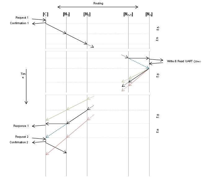
Example
The next figure shows processing UART Write & Read request. The DPA Request is marked Request 1. It writes 5 bytes of data to [Nn] UART peripheral, it waits 20 ms, and then it reads a number (unknown in advance) of bytes back from the UART peripheral. The network is operated at STD mode.
After sending Request 1 to the [C] the [C] replies by Confirmation 1. The DPA Confirmation reports q hops to deliver a DPA Request from [C] to [Nn] with a timeslot of 40 ms and also r hops to deliver the response back from [Nn] to [C]. After the DPA Confirmation is sent the [C] transmits the RF packet to the network (1st hop). The packet is received by [N1] and [N1] routes the packet further (2nd hop). The routed packet is received by [N2] as expected. The routing continues. Last but one [Nn-1] receives the routed packet and because of positive RF conditions and network topology the routed packet is also early received by the addressed [Nn]. Then [Nn-1] makes the very last routing but [Nn] does not receive the packet again.
Then DPA writes 5 bytes of data to the UART, waits another 20 ms, and reads data from UART. In our example total of 20 bytes is read which results in the real timeslot of 50 ms to be used to deliver the response back from [N3] to [C].
Then [Nn] waits for the still running routing to finish. After that [Nn] transmits the response packet to the network (1st hop). The packet is received by [Nn-1] which routes the packet further (2nd hop). The routing continues. The routed packet is received by [N2]. [N2] routes the packet to [N1]. The packet is also received by [C]. [C] immediately delivers Response 1 to its interface. At the same time [N1] finally routes the packet to the [C] which receives it but identifies it as the already received response thus [C] does not report it to the interface again.
The optimistic response time is:
( ( q + 1 ) × 40 ms ) + 20 ms + ( ( r + 1 ) × 40 ms )
The pessimistic response time is:
( ( q + 1 ) × 40 ms ) + 20 ms + ( ( r + 1 ) × 60 ms )
But the real response time was:
( ( q + 1 ) × 40 ms ) + 20 ms + ( ( r + 1 ) × 50 ms )
An optimistic response routing scenario is represented by dotted green arrows (potential 40 ms timeslot) and a pessimistic scenario is shown by dotted red arrows (potential 60 ms timeslot).
The next Request 2 cannot be sent to the network immediately after Response 1 is received. The RF collision would occur. Request 2 can be issued after the actual routing finishes (end of the dotted blue arrow) the soonest. Another approach is to send the next DPA Request to the [C] after the pessimistic (using the longest 60 ms response timeslot) is finished. For many applications that do not have to be time optimized this is the reasonable and easy to compute way of timing.
Throughout the document in the following examples of the DPA communication, the DPA Confirmation is not usually stated as the emphasis is put on DPA Request-Response pair messages.
The following video depicts a unicast communication in the
IQMESH network.
DPA Notification notifies a connected master device at the [N] side that there was a DPA Request without a “read-only” (can be configured by EnableIFacenotificationOnRead) side-effect processed by the [N]. It consists of the same foursome that was part of the original DPA Request except for NADR that stores the address of the sender, not the addressee, and the HWPID that contains the actual HW Profile ID of the device. DPA Notification is therefore always 6 bytes long. DPA Request is considered “read-only” when the corresponding DPA Request returns some data, otherwise, it is considered a “write” request.
DPA Notification is issued to the connected master interface when DPA Request is sent from the [C] or when the DPA Request is part of the FRC acknowledged broadcast (see Acknowledged broadcast - bits and Acknowledged broadcast - bytes).
DPA Notification is not issued in the case of DPA Request invoked from a local interface, from DpaApiLocalRequest, or predefined FRCs Memory read and Memory read plus 1.